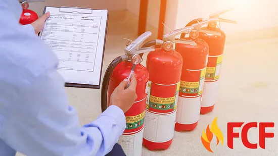
Draw a fire extinguisher showing all the spare parts
#1.Discharge hose:
This allows the inside extinguishing agent to travel across the tank and reach the base of the burning fire. Always aim the flow of the agent in the targeted direction.
#2.Nozzle:
This is the conical end of the hose and through it the extinguishing agent disperses.
#3.Pressure gauge.
It is a small circular gauge attached to the outer portion of the value assembly. It has a clock like arrow showing pressure bar and a green and red portion.
The gauge maintain the pressure when discharging the agent during the time of fire. When it is properly charged then the arrow of the gauge is green. If the needle arrow is to the right of the green, it means its overcharged and it might explode. If it is to the left, it indicates that it is discharge or there is no pressure.
Note: a pressure gauge is not present in all Co2 extinguishers
#4.Pull pin:
It is the locking pin and inserted into the value portion to prevent accidental squeezing.
#5.Carry handle:
The handle allows the user to easing grasp, lift and carry the extinguisher.
#6.Operating lever:
It is a metal piece that is pressed to operate the fire extinguisher. The lever can only be operated when the pull pin is removed.
#7.Tamper seal:
It helps in keeping the pull pin in place.
#8.Instruction label:
All fire extinguishers should have the instructions on how to use it and on what type of fire class it should be applied. Note: only a skilled and trained person should use it.
#9.Monthly /quarterly /annual inspiration, testing and maintenance tags/stickers
These ensures that the extinguisher is properly handled so that it operates effectively when needed.
Fire extinguisher are capable of suppressing small fires especially when it is at its incipient hence saving people from injuries, death, asset, property and environment destruction.

